Monday 2 December 2019

ARCH 653_ Project 2_ Dynamo Parametric modeling


Watch the Video:


The goal of the project is to use Dynamo to automate the parametric modeling in Revit.
For this project, I used Refinery, an optimization node that contains a Multi_objective optimization algorithm.
In this project 2 shading parameters are controlled in Dynamo.
1. Opening factor
2. Width factor (B_factor)


For the mass model, a simple cylinder is considered and the adoptive components (shading panels) are mapped to the surrounding surface of the cylinder.


Steps:

1. Exporting the coordinates of the panels using exporting data node in Dynamo.
2. Open a new project and load the desired adaptive component to the project
3. Import the edited SAT file using Dynamo.


4. Getting access to the parameters of the adaptive component by name


To get the parametric values for the opening factor, the following steps are done:

1. Find the normals of each panel

2. Use 3 variables (x,y,z) to create dynamic sun vector position.
In this step instead of using the Revit sun path, a sun vector is simulated in Dynamo using sun position information in Revit. The reason is to use those variables as input for Refinery optimization.


3. The angle between the sun vector and normals of the panels are then calculated through dot product and the values are remapped to be used as opening factor value


The same values are used for overriding the colors of the panels based on the angle between the normals and the sun vector.


To get the parametric values for the width factor (B_factor), the following steps are done:

1. Drawing a mass model in the Revit project. This model is considered as the adjacent building to my project.

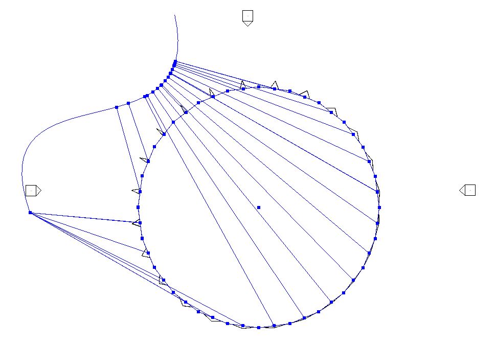
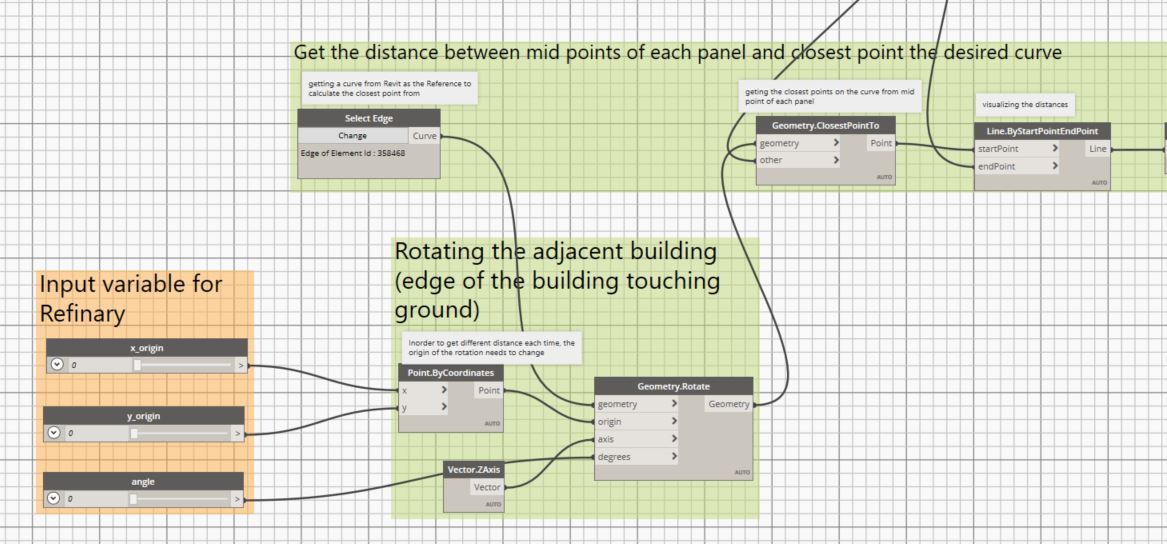
2. Use the edge of the mass model as a reference to calculate the distances between the midpoints of the panels and the closest points of the curve (building edge). In this case, I chose the edge that faces my project and touches the ground as the reference curve.


3. Get the distance between midpoints of the panels and the closest point on the selected curve


4.  Use the remapped values to control the width factor of the panels

In order to get different distance values to later used for Refinery, the location of the curve changes through rotation.
3 variables are used as input:
x and y to change the origin of the rotation
angle: to change the rotation angle


Two objectives are used for Refinery:

1. Maximizing the sum value of the opening factor values
2. Minimizing the sum values of the width factor values

The project is exported for Refinery.


The optimization process is done with 48 population size and 200 generations.


These solutions show the Pareto front solutions in 200 generations regarding the defined objectives.
Any solution could be selected to be shown in the project and the corresponding variables could be extracted. The image below shows one solution selected in Refinary.


Findings:

Unfortunately the Refinary cannot show the objective space. The values of the objectives are not presented in the solutions yet.


Monday 28 October 2019

ARCH 653_Project 1_Revit Parametric Modeling

ARCH 653_Project 1

Chameleon Biomimetic Mixed-Use Office Building

WWF Architects Designs 


Courtesy of  WWF Architects Design
First prize-winning competition project
Dubai
Year: 2015
GFA: 17,716 m²
Use: mixed-use building, office
Architecture Team: Hannes Werner |Javier Angel |Wolfgang Regner I Rima Obeid | Marina Eremija
Facade Design: Wisam Allami | Hatem Al Khafaji
3D Visualization: Hatem Al Khafaji | Josephus Taboada

To see more images and renders of the project please click on the supporting links:
chameleon bio-mimetic mixed-use office building


Revit Modeling:
1. Mass modeling: Conceptual mass.rft
2. Pattern modeling: Curtain Panel Pattern Based.rft

The mass modeling includes the following steps
1.1 Creating the required reference plans based on the floor plans 
1.2. Drawing plan outlines 
1.3. Defining parameters
1.4. Dimension constraint (length, width, height, angle) 
1.5. Assign dimensions to parameters


    Create mass through extrusion and boolean
    Assigning the extrusion height to the height parameters. 


1.6. Divide surfaces and select the required pattern. In this case "Triangle(flat) is selected. 


Note: Sets of parameters are defined for the pattern. 
The facade pattern is a hexagon pattern consists of 6 equilateral triangles in 3 layers of glazing, shading, and structure.
Courtesy of  WWF Architects Design

One equilateral triangle is modeled as a module for the facade. The U-Grid and V-Grid parameters are defined to make the original triangle pattern equilateral based on the bisector equation in an equilateral triangle. The same numbers are then used for the pattern.rft file.

2. Pattern modeling: Curtain Panel Pattern Based.rft

2.1. Using the same number of U_grid and V_grid for vertical spacing and horizontal spacing accordingly.
2.2. Create an instance base parameter the same as the Base in the mass model and check "Reporting Parameter". The values of the Base parameter in both models should match.


2.2 Creating the glazing layer 
2.3 Creating the shading layer


2.4 Creating the shading layer

Curtain panel parameters:
Different parameters are set to make the pattern module dynamic, including the opening and closing scale of the shadings, the depth of the movement of the shadings, the distance of the shading from the glazing and the distance of the structure from the shadings. 
the material parameters are also defined as a placeholder and the corresponding masses are assigned to. These parameters will be assigned again to type parameter in the mass model in order to pass them at the project level.

After the modeling is finished, the pattern is loaded into the mass model.

Creating material type parameter and assign the patterns' materials to them so they could be passed to the project level.

A simple glazing pattern has also been loaded to the mass model for the fist floor facade pattern.
Finally, the mass model is loaded into an architectural project Revit file (.rvt)

Other steps:
- Transfering the mass model to a project model with floors (5 levels), Roof and walls.
- Assign the materials
- Drawing the plan floor layout and place furniture
- drawing the topography and site plan

 Renderings:


Watch the video: